
MILA Launch Operations
|
MILA from the air. Photo from TIB Vol 5, No 6. |
This text is from MSFN Technical Information Bulletin Volume 5, Number 6, 15 March 1968.
Merritt Island plays the same vital role in supporting orbiting spacecraft as other MSFN Apollo stations, but, in addition, plays a unique and critical part in prelaunch testing of the spacecraft and protection of the astronauts.
MIL has been set up to function basically as a MSFN remoted station using the Downrange Uplink (DRUL) system for UHF command through CNV, GBI, and ANT. In providing orbital mission support, MILis configured basically as other USB stations.
In addition prelaunch support for KSC and MSC required that other equipments be installed at the stations.
To support prelaunch operations, MIL has an additional PCM decommutator, telemetry “fine monitor” display, a set of flight control consoles, an acquisition system which interfaces with ETR instrumentation, enlargement of the 1218 system for command history, an abort advisory system, an enlargement of the air/ground voice system, and a telemetry data system for interfacing with the space vehicle.
Also, additional communications include 24 voice circuits to KSC, 5 to ETR, 11 to MSC, and 4 to GSFC; 8 wideband circuits to and from KSC; three 2.0 kbps data modem circuits to ETR and one 40.8 kbps data modem circuit from ETR; two 3-kHz circuits to ETR; three event circuits for KSC and MCC-H and two event circuits from ETR.
During prelaunch operations MIL provides support to KSC for certain data needed to certify that the launch vehicle and spacecraft are ready for flight; provides support to MSC in the integration of the space vehicle with the flight control systems of MCC-H; and provides support to the KSC to assure software and hardware compatibility between the flight systems of the space vehicle and the ground systems of the MSFN and MCC-H.
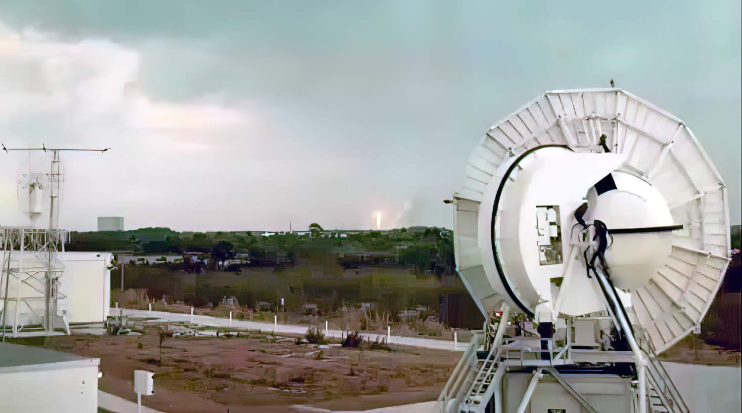 |
The launch of Apollo 8 as seen from MILA. Enhanced frame grab from a poor quality copy of a NASA film. |
MIL systems designed to protect the lives of the astronauts in the event of a hazardous booster condition during launch are perhaps the most critical equipment.
The escape system, which will lift the command module clear of the booster, can be controlled from Mission Control Center, Houston, and by the appropriate blockhouse at Cape Kennedy. The launch display and control point at Cape Kennedy is the Launch Operations Manager (LOM) console which provides continuous monitoring by the Abort Advisory System (AAS) of all launch events to detect the first indication of an emergency situation. If an abort of the launch is warranted, the Launch Director will initiate an abort “request” (manned flights) or an abort “command” (unmanned flights).
The abort “command” will immediately activate the spacecraft escape tower.
The abort “request” signal will illuminate lights in the spacecraft and the astronauts will manually initiate the escape system.
Two commands are required for the request or command and are designated “Abort A” and ”Abort B.”
These extremely critical signals must be transmitted reliably from the Launch Director's Console in the blockhouse to (MILA) command system for transmission to the spacecraft.
The commands are sent over six transmission lines as de levels of 48 µsec minimum duration. The resulting signals are received at the USB station by the Abort Interface Unit (AIU).
The AIU senses and decodes the six command channels, verifies valid commands, and generates the proper interrupt to the MIL 642 B command computer which will uplink the command. After the spacecraft receives the command, the 642B command computer will, by two special codes, inform the AIU of an Abort A or Abort B successful trans-mission. The AIU, in turn, will illuminate lights on the blockhouse LOM console with single channel dc switching.
Additional events transmitted by the AIU are activation of the escape system and status of the UHF and USB command.
Because of the critical nature of the system, particularly the command portion, special measures were taken in the design to ensure reliable transmission of commands and at the same time protect against erroneous commands being generated by equipment due to failure or noise on the transmission lines. The transmission system utilizes protected and dedicated circuits and voting logic.
Voltages on two of the three command lines are required to generate the command, providing that the other set of three lines are not active at the time. A single open line will still permit successful operation. Likewise, noise or signal voltage on a single line or all lines simultaneousIy will not result in a valid command, nor will failure of an component of the system.
___