A
Technical Description of Honeysuckle
Creek
During the Apollo Era
by Hamish Lindsay
 |
|
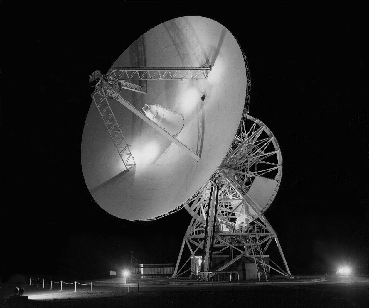
The Honeysuckle antenna by night. Photo by Hamish Lindsay. |
The original Project Mercury
stations such as Muchea, near Perth in Australia, were mostly built from off
the shelf and military equipment, progressing to a more substantial installation
for the Gemini Program.
The stations consisted of individual systems spread around the site, each with their own antenna slaved to the radar. A skin tracking Radar, a Command System incorporating Voice uplink, and a Telemetry System incorporating Voice downlink and Medical Data channels provided the required contact with the spacecraft.
These stations were good enough for earth orbit passes,
but the long tracks and distances to the moon were a different matter, and
a sophisticated system was developed from the Deep Space technology used by
the Jet Propulsion Laboratory of Pasadena, California. It became known as
the Unified S Band, or USB, system, working in the S Band 2
– 4 GHz part of the frequency spectrum. Apart from being a very compact
integrated system, it only needed one antenna. Honeysuckle Creek was not a
radar station. Both the Mercury and Gemini tracking stations had skin-tracking
radar for tracking passive targets. To track any spacecraft Honeysuckle had
to have specially designed compatible antennas and transponders in the spacecraft
to turn the signal around for retransmission back to the station.
Mercury and Gemini were only Earth orbit missions up to a maximum elapsed
time of 14 days. To us on the ground all the missions were brief (up to 12
minutes) passes while to the astronauts they only had contact with the ground
when they were over a tracking station. Those passes were normally a flurry
of activity as verbal information was passed back and forth, telemetry filled
the station with spacecraft data, and the surgeons conducted constant medical
checks on the astronauts. Highly trained Flight Control teams were deployed
to stations around the world to control each pass from the station. Mission
Control (initially at Cape Canaveral before moving to Houston) had to contact
the spacecraft through the local station Capcom.
With the arrival of Apollo, three stations with 26 metre dish antennas were
spaced around the world at Goldstone in California, Madrid in Spain, and Honeysuckle
Creek near Canberra, Australia, to provide continuous 24-hour coverage of
the Moon. Smaller 9 metre stations supplemented these bigger stations to fill
in the gaps during the earth orbit phases of the missions, and for tracking
the Apollo Lunar Scientific Experimental packages (ALSEPs), of which Carnarvon
in Western Australia was an example. The neighbouring Deep Space station DSS42
at Tidbinbilla was modified to perform all the USB functions so that two spacecraft
could be tracked independently. It was called the “Wing Site” while Honeysuckle Creek was called the “Prime Site”. Tidbinbilla
also acted as a back up in the case of a complete failure by the Honeysuckle
USB equipment, which actually happened during the Apollo 8 mission when Honeysuckle’s
antenna went down.
During the Apollo program the tracking stations became just a communications point between the Mission Control Center at Houston, Texas, and the spacecraft, relaying voice and commands from the Control Center, and receiving voice, telemetry (which included the biomedical data), and video from the spacecraft for transmission back to the Control Center by undersea cables or satellite. This was quite a different philosophy from the Mercury and Gemini missions, as no NASA personnel were present on site for the missions. The long tracks on the way to the Moon were a world away from the earth orbit style missions.
Honeysuckle (and the whole network) answered to two separate NASA institutions in America –
All the engineering and technical operations were controlled by the Goddard Space Flight Center in Maryland. For instance they conducted the simulations before each mission to check the station was ready both technically and procedurally.
Then before each mission Honeysuckle Creek and the whole network of stations were handed over to the Mission Control Center in Houston, Texas, and the Flight Controllers ran their own checks and simulations before running the missions through the tracking stations.
OPERATIONAL AREAS WITHIN THE STATION:
The tracking operations were divided into clearly defined areas, both electronically
and physically. At the front end was the Antenna, located as
accurately as the surveying methods of the time allowed. Later, using spacecraft
and Very Long Based Interferometer (VLBI) techniques the antenna was located
more accurately. Under the antenna dish was a room containing the Power
Transmitters, sensitive Receivers, and the Cryogenically
Cooled Parametric Amplifiers. A hydraulic Servo System
moved the antenna.
A large room in the operations building, facing the antenna, was known as
the USB Section. It had the only window in the operations area,
for the servo operator to see the antenna, and contained the servo console
and computers to control the antenna, the receivers to tune into and amplify
the signal, the subcarrier data demodulators, station time standard, and the
ranging system.
Next was the Telemetry Section with all the signal processing
and recording equipment for the data from the astronauts and spacecraft, followed
by the Computer Section to act as a digital interface between
the station equipment and the communication channels to the outside world.
A Communications Section handled all the voice and teletype
traffic, the internal intercom system, and the data streams in and out of
the station, including a microwave link across to Tidbinbilla.
An Operations Section tied all these areas together and organised
the mission activities, tests, and interfacing with Mission Control Center
at Houston. They worked from a special console next to the computer section.
A Facilities Section in a separate building provided all the
station power. As it all had to be 110 volt, 60 Hz mains for the American
equipment, and reliability and remoteness were also factors, all power was
generated by Caterpillar diesel engines on site. There was a small Management
and Administration section, which included a Logistics
Section, or store, for spare parts and equipment.
THE USB SECTION:
Let’s explain what all these operational sections do, beginning with what we called the front end, the USB Section, and its prime responsibility, the signal to and from the spacecraft. Let’s look at the 26 metre parabolic dish Antenna first.
The Antenna
The 26 metre diameter antenna used what was known as an XY
mount, which meant the antenna could tilt in two directions, north
to south, and east to west. Combining the movements, almost the whole sky
could be covered, only a small section known as the "keyhole" in
the east and west direction was blind. This limitation only affected some
AOS and LOS times by a few minutes. The XY mount allowed the antenna to track
fast spacecraft smoothly over the station’s zenith. An azimuth/elevation
mount would lose a fast moving target tracking through zenith as the servos
would have to swing the antenna rapidly through 180 degrees at zenith.>
Beamwidth: 0.43 +/ 0.05.
Pointing accuracy: 40 seconds of arc.
Maximum tracking rate: 3 degrees per second.
Polarisation: Right Hand Circular, or Left Hand Circular, remotely
switchable.
Gain: 51db up, 53db down.
Acceleration: 5 per second
A small 2 metre
dish located at the apex of
the quad legs was known as the Acquisition Antenna. With
a wider 3 degree beamwidth it was only used for relatively strong signals
from fast moving earth orbiting spacecraft to initially locate the signal
from the spacecraft and steer the main Antenna onto the target.
It was also used for tracking aircraft during simulations and tests, where
there were no accurate predicts. Once we had to resort to using a person standing
outside the window pointing at the aircraft with their arm!
The procedure at Honeysuckle to acquire a spacecraft was first to receive
a computer generated acquisition message from the Goddard Space
Flight Center, which set the antenna angles to time, and the antenna was slaved
to the Antenna Position Programmer (APP) (basically a dedicated computer to
drive the antenna servos). For strong signal, fast moving targets the acquisition
antenna was used first because of its wider beamwidth. As soon as
the receivers had locked on to the signal, the antenna began tracking the
spacecraft, and the angles were sent in real time to Goddard to update their
maths model. At lunar distances the operator would go from computer (APP)
control straight to Autotrack on the Main Antenna. When the
servo operator felt the signal was solid enough, and the receivers were locked
onto the signal, he would switch over to the main antenna (0.43 degrees beamwidth)
and go into Autotrack mode which was how the pass was conducted.
If the signal dropped out, or became noisy (Apollo 13 for example) the servo
operator would immediately switch back to computer control until contact was
re-established.
Predicts.
Due to the narrow beam width of the antenna, it had to be extremely accurately
pointed at the target. To achieve this, computers at the Goddard Space Flight
Center (GSFC) calculated the spacecraft's position and trajectory from previous
tracking data and the result was modified for the tracking station’s
location before being fed to the station down the NASCOM communication lines
at least 30 minutes before the spacecraft was due. These were known as predicts.
A Univac 1218 Computer
in the Computer Section received these predicts and produced a paper tape
for a special processor called an Antenna Position Programmer (APP)
which interfaced directly with the Antenna Servo System to
drive the dish. Once the spacecraft had been acquired using the computer instructions
to point the antenna, the normal procedure was to switch the antenna drive
from Program to Autotrack to follow the spacecraft's
signal. For Deep Space work the antenna remained in program track due to the
low level signals, and could be offset from the calculated command angles
to maximise the signal, if required.
 |
|
UNIVAC Type 1218 Computers (April 1972) Shown here is a Type 1540 dual magnetic tape unit on the left with a Type 1218 computer (32k memory) on the right and a 1218 computer (16k memory) in the centre. The 16k computer received antenna prediction data via a NASCOM teleprinter and processed it into a series of antenna pointing angles (X and Y) at one second intervals on a teletype punched paper tape. This drive tape was used by the Antenna Position Programmer to aid in spacecraft acquisition and as a backup in the event of an auto-tracking failure. The 32k computer, being operated by Bryan Sullivan, was used either as a spacecraft telemetry monitoring processor, as a spacecraft digital command simulation system or as a backup to the 16k computer. System software was loaded via the magnetic tape units. Polaroid photo probably taken by Hamish Lindsay. See also under the Computer section below. |
Once the station had locked onto the signal, another special processor called a Tracking Data Processor, (TDP) accepted the ranging data, the speed of the spacecraft relative to the station from the doppler, and the antenna angles relative to the station's geographical location, and coded this information for transmission to Goddard. It was coded in both high-speed data at 2,400 bits per second and in teletype code onto paper tape.
COLLIMATION TOWER:
Located on a nearby mountain ridge to the west was a tower, known
as a Collimation Tower, with special equipment and antennae
to simulate a spacecraft, so the main antenna could be pointed at it to run
tests on all the transmitting, receiving and processing equipment. Before
every pass all the equipment was checked out on the Collimation Tower. If
a problem appeared while tracking a spacecraft, the station could quickly
check out all its systems by going to the tower and running tests to confirm
whether the problem was in the station or in the spacecraft.
 |
|
The Collimation (Coll) Tower. Photo: Hamish Lindsay. |
The Uplink, or Transmitted Signal:
Both the uplink and down link signals were modulated onto a single carrier.
The uplink was less complicated than the downlink and consisted of Voice,
Commands, and the Ranging code. Both the Prime
and Wing sites could transmit two uplinks simultaneously for either a backup
in case of failure of the link in use, or to transmit to two spacecraft within
the antenna beamwidth at the same time.
Voice:
Speech was regarded as the prime uplink signal, and simply stated, provided
a telephone link between the Capsule Communicator (Capcom)
at Houston, always one of the astronauts, and the astronauts in the spacecraft.
A Communication Technician (Comtec) at the tracking station
monitored all the traffic and checked the best channel was being used. The
baseband voice signal was analog with a frequency response of 300 to 2,550
Hz modulated on to a 30 kHz subcarrier, summed with the other uplink signals,
and phase modulated onto the carrier.
Commands:
Commands consisted of instructions to the spacecraft, primarily to relieve the astronauts of irksome chores. Examples were antenna switching for the optimum signal strength at the ground station, recorder control for transferring information stored on magnetic tape from the spacecraft to the ground, and the more important navigational data to update the command module/lunar module computers.
Commands were loaded into the station’s Univac 642B Command Computer by high speed (for the time) data lines from Houston. These were transmitted with a digital code of 57 bits at a rate of 4.8 kilobits per second.
Commands could be called up for transmission to the spacecraft at a designated time, or be sent in real time. Instructions to transmit a command were initiated in Houston, and the 642B computer recalled the required command from memory and transmitted it to the spacecraft, where a digital word was returned with the telemetry stream back to the computer. If the computer received no return word, it would retransmit the command a predetermined number of times before raising an alarm.
A command would leave the
computer in a 30 bit parallel code, was converted to a serial phase shifted
keyed (PSK) waveform consisting of a 2 kHz data signal combined with a 1 kHz
reference. This baseband command signal was first frequency modulated on a
70 kHz carrier before being summed with the other uplink signals and phase
modulated onto the carrier.
Ranging:
Ranging was a code transmitted to the spacecraft and returned for time comparison with the original code. The pseudo random noise range code, generated by a dedicated ranging system, was a combination of 5 codes to form a 5.4 second period code of 5,456,682 bits, which gave a maximum unambiguous range of 804,650 km, or twice the distance to the moon.
Ranging was initiated manually by the Ranging Technician after the station was locked onto the signal from the spacecraft, and once acquired by the code, was updated by doppler only. Resolution within the Ranging System was +/ 1 metre, but system jitter and ground instabilities gave an overall accuracy of +/ 15.2 metres.
The range code was summed
with the other uplink signals and phase modulated onto the carrier.
As stated earlier, there were two uplinks to cover two spacecraft, the final
modulation process used phase modulation with relatively narrow deviation
to ensure a phase stable carrier component arrived at the spacecraft, as the
spacecraft transmission carrier was derived from the received carrier through
a transponder. The total RMS phase deviation on the uplink carrier was kept
at about 1 radian.
The command subcarrier of 70 kHz and voice subcarrier of 30 kHz were combined in a subcarrier oscillator system, and delivered to the exciter as normal modulation, phase modulated on the S Band carrier. The frequencies used are shown in the diagram.
The Power Amplifier used a klystron and delivered a continuously variable CW output of 1 to 20 kilowatts. The bandwidth of 10 MHz was wide enough to accommodate both uplink frequencies. 500 milliwatts drive was required to produce the full 20 kilowatts output into the antenna.
The Downlink, or Received Signal.
The spacecraft downlink S Band signals could be received at the antenna at
levels varying from -150 to -90 dbm. The signals bounced off the parabolic
aluminium dish surface to the Hyperbole Focus where the feed
system was split into four parts, giving a Common Monopulse Tracking
System of left or right circular polarisation, remotely selected.
The sum output of the Monopulse Comparator was fed into
a Cryogenic Parametric Amplifier (Cooled Paramp) with a low
system temperature. This Paramp output was split 5 ways, 4 to independent
phase locked Receivers, switchable between 1 kHz to 12 Hz, allowing the receivers
to track down to a level of 160 dbm.
The “X” and “Y” outputs of the Monopulse Comparator were
fed to a triple channel Warm Paramp, and then to Tracking
Receivers whose reference was derived from the original sum channel.
The remaining channel of the warm Paramp was used as a backup for the main
cryogenic Paramp.
The function of the Diplexer (together with the band pass and
reject filters) was to combine the uplink and down link frequencies, giving
a rejection of 180 db in the receive spectrum.
Receivers:
The S band frequency from the Cooled Paramp was converted down to an IF of 50 MHz, and then reconverted to a 10 MHz reference frequency. Phase detection at this frequency drove programmable local oscillators and multiplier chains for the phaselocked operation. The outputs from the Receivers, of 50 MHz and 10 MHz were composite signals which were fed into the Subcarrier Data Demodulator System (SDDS) where the various channels of information were stripped off and patched to the appropriate areas determined by the Operations Supervisors.
 |
|
A view looking along the USB racks. On the left is the System Monitor, a chart recorder logging all the equipment parameters alongside a time code. Alongside is a rack for remote control of test functions. Next are the two Power Amplifier controls that send the signal up to the spacecraft. The next rack is the Exciter control for controlling the uplink to the spacecraft, followed by four Receivers to receive the signal from the spacecraft(s). In the background Peter Gavin is wrestling with a problem, while Kevin Gallegos is sitting in the SB1 position wondering why I am wasting my time taking photographs. Photo and text: Hamish Lindsay. |
Subcarrier Data Demodulator System (SDDS):
The Subcarrier Data Demodulators accepted the composite signals
from the Honeysuckle Creek, Tidbinbilla, and Parkes Receivers. They contained
the voice, telemetry, biomedical, and television signals and broke them down
into a Pulse Code Modulated (PCM) bit stream, Voice
and Biomedical data. These were patched in both PM or FM
modes as dictated by operational requirements.
The Television signals, which were frequency modulated directly
on the carrier in the spacecraft, entered via the 50 MHz FM channel and were
completely demodulated and fed to the television processing equipment.
Voice:
The voice from the demodulators was fed to the Communications Technician
(Comtec) who monitored and switched for the best signal source. The
voice was recorded on analog reel-to-reel magnetic tape recorders as well
as being sent in real time to Mission Control at Houston via PMG (now Telstra)
circuits. In Australia the then Overseas Telecommunications Commission then
passed it over to the USA via undersea cable or satellite.
TELEMETRY SECTION:
Telemetry Data.
The telemetry PCM bit stream was routed to 4 Decommutators
in the Telemetry Area. The rates were variable, normally
high at 51.2 kilobits and low at 1.6 kilobits/ second. The telemetry data
was recorded onto reel-to-reel magnetic tape data recorders.
The prime function of the PCM Decommutators was to present all
the decoded data to the Telemetry Univac 642B Computer
in 30bit parallel form for transmission to Houston. They also allowed station
personnel to monitor selected data on indicators or chart recorders.
The PCM telemetry could be broken down into 6,400 words of information on
the spacecraft antenna direction, physical condition of the astronauts in
the CSM, quantities of consumables, engineering data, etc.
Biomedical Data:
The Biomedical information was in two distinct paths.
One was used for the Command Module when the data came via Pulse Code Modulated (PCM) telemetry.
The other path was used while the astronauts were in the LM, or in their spacesuits during the lunar walks. The LM biomedical data was routed down separate analog FM telemetry channels to special processing equipment, which converted the analog information to digital for the computer.
Both sets of information, together with the other PCM data were presented
to the Univac 642B computer for transmission to line.
 |
|
This diagram – of communication requirements during the Apollo 15 mission – gives an idea of the complex configurations needed at Honeysuckle. Illustration by Hamish Lindsay. |
 |
| This diagram shows the links necessary to support the CSM as well as the Lunar Module and astronauts on the Lunar surface. (This does not include the Rover as on the later J missions.) |
TELEVISION:
The television signal from the spacecraft in the later Apollo missions
was the American standard of 525-lines/60 field frame sequential colour television,
and it also contained information on the television camera temperature or
battery voltage. This television signal from the demodulators was presented
to a matrix switch, which selected the best signal from the
participating stations. The voice and telemetry subcarriers
were filtered out with a subcarrier cancellation device, which eliminated
the subcarriers by a locally generated subcarrier locked to the incoming signal
and 180 out of phase with it.
The signal was cleaned up and processed in a standard television processing
amplifier before the vertical interval test (VIT) signals, multiburst, and
gray scale were inserted on line 16 and 17 of the vertical blanking period.
The television signals were recorded on Ampex VR 660 and
VR 1100 video recorders. In Australia the composite processed television
signal from the Honeysuckle Creek and/or Tidbinbilla stations were monitored
on a modified Conrac colour monitor and transmitted to the specially
prepared video centre in Sydney. The Parkes signal was sent directly to Sydney
where NASA operators selected the best signal for transmission direct to Houston,
with a split to the local network.
 |
|
Ed von Renouard at the video console during Apollo
12. |
Ed von Renouard, the Television technician at Honeysuckle Creek in the Apollo flights offers the following comments on the Apollo television system:
“The spacecraft television on Apollo 11 had three modes. Mode 1 had a horizontal resolution of 212 lines with a bandwidth of 2.6 MHz and a vertical resolution of 218 lines with a bandwidth of 2.7 MHz at 10 frames per second and was the system used for the public broadcasts. Mode 2 was called the 5/8 per second mode, a scientific system that was never used publicly and built a picture over 5/8th of a second. It had a horizontal resolution of 848 lines and a vertical resolution of 874 lines.
The RCA Scan Converter for Apollo 11 operated on the optical conversion principle, that is the narrow band slow scan television (SSTV) down link picture from the Lunar Module at high resolution (848 lines) and 10 frames per second was displayed on a black and white 10 inch monitor and scanned at the US (EIA) TV standard of 525 lines and 60 frames per second by a Vidicon camera, from where the 10 original frames per second were recorded on a magnetic disc whilst simultaneously going out live to Sydney and Houston, and were then replayed five times from the disc to make up the 60 frames per second. This replaying delay, incidentally, is the reason why the pictures seen by the public were so smeared and ghostly when the astronauts moved.
The original idea of mounting the television camera upside down in the MESA (Modular Equipment Storage Area) was to simplify its removal by the astronaut. When the astronaut removed the camera to plant it on the lunar surface it would be right way up. A few weeks before the Apollo 11 mission someone at NASA spotted the camera would be upside down in the MESA so a modification to install a toggle switch connected to the deflection coils of the camera by means of a relay inverted the picture by the simple expedient of reversing the vertical scans.
Every fifteen minutes during the whole period of the moon walk and the subsequent three hours of video and telemetry down link until we lost the signal we had to change the inch magnetic tapes on the Ampex 1400 instrumentation recorders which recorded the telemetry from the spacecraft and the astronauts, and also the slow scan television at a speed of 120 inches per second. The converted commercial standard television was recorded on an Ampex VR1100 four head video recorder using a 2-inch (5 cm) tape, which decided to choose this mission (Apollo 11) to develop an intractable and elusive fault. It started to overheat and blow fuses so I had to place a fan blowing on it to keep it cool until the end of the mission.
In later Apollo missions with full commercial standard television from the moon, Ampex VR660 helical scan two-head video recorders using 2 inch tape were used with a Wollensak one-inch helical scan recorder as a backup more than ten years before helical scan VCRs became available to the general public.
For Apollo 12 the scan converter was no longer used, as a more powerful transmitter on the Lunar Module, EIA standard frame sequential television was down linked from the moon. The colour was produced by means of a red, green, and blue colour wheel rotating at 20 frames per second in front of a black and white Westinghouse television camera used by the astronauts, which was then electronically converted at the tracking stations to the standard commercial broadcast signal, colour synchronised to the green field, before it was sent to line.
By Apollo 15 the television
system was properly installed without ‘kluges’ and modifications,
and from then on worked very well, though still using the colour wheel.”
COMPUTER SECTION:
As the data lines between the station and Mission Control Center in Houston
had limited capability for data transmission in those days, all the telemetry
was presented to the Telemetry Univac 642B Computer, where only
data selected by the Flight Controllers in Houston was transmitted to line.
The output from the computer of 30bit parallel words was converted to a serial
bit stream of 4.8 kilobits per second and transmitted to line.
Both Command and Telemetry Computers were identical
and interchangeable and had 20 input and 20 output channels, 32k memory and
Univac 1540 duplex magnetic tapes, each with 4 tape transports. Between them
was an Expanded Memory Unit (EMU), which increased each 642B
computer’s memory capacity to 64k. As well as the Antenna 1218 computer
with a memory capacity of 16k already referred to, there was a Univac 1218
computer with 32k of memory called the ASTAM computer to support ground
simulations.
Programs used during the mission were sent from Goddard Space Flight Center
in Maryland, USA, in real time and on magnetic tape and paper tape to be loaded
into the computer at predetermined times. Apart from holding the mission operational
programs, the Univac 1540 Magnetic Tape Units were also used for fault analysis
and storing data.
 |
|
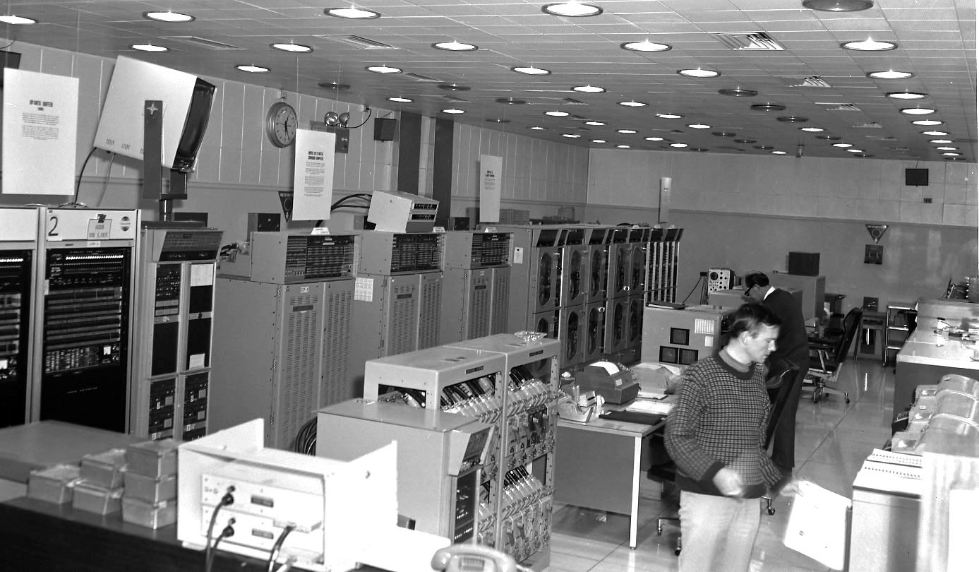
The computer room with John Saxon in the foreground and Geoff Ruck behind. On the left is the Updata Buffer, the interface between the Command Computer and the RF transmitters in the USB area, next are the two Univac 642B computers with the Expanded Memory Unit between. Further along the row are the Magnetic Tape Handlers with the Univac 1218 computers at the far end. Consoles with paper tape handlers, keyboards and teletypes etc. to access the computers are down the centre. Photo and text: Hamish Lindsay. |
TIME STANDARD:
All the activities of the missions revolved around time, and the tracking stations had dual time standards located in the USB area, which provided multiple readouts, pulses and various coded times for time tagging all data produced on the stations. Three main forms of time were displayed around the operational areas:
Universal Time UT
also known as Greenwich Mean Time, GMT, or Zulu time, was used by everyone
in the mission as a common time reference. The stations had digital readouts,
and analog 24-hour dial clocks with two-hour hands to show both Universal
Time and local time.
Ground Elapsed Time, or GET was also used by all the mission
people as a planning and event time. The Flight Plan for the whole mission
was planned months before using a time that began from zero at lift off. The
GET clock started as a minus count before the mission, ending as the familiar
"Three Two One We have lift off," and the moment the spacecraft
left the ground this clock would count through zero and begin counting up,
and continue counting in hours until the end of the mission. All participants
in the missions knew exactly where they were in the mission from the GET.
Horizon Time was used only by the tracking stations, and gave
a reference for events on the stations for every pass. For earth orbit passes
for instance, it would begin at H30, or 30 minutes before the spacecraft was
due to appear on the horizon, and count down to zero when all the spacecraft
signals should appear in the equipment, then count up until 10 minutes after
the end of the pass, when it would be reset to minus 30 minutes ready for
the next pass.
Accurate time was essential, and various methods were used to keep the station
time within 10 microseconds of Universal Time. WWV, or WWVH
were used for a coarse check, but for a vernier adjustment down to +/ 10 microseconds,
100 kHz Loran C navigational signals were used. The North West
Pacific Loran C chain was the nearest to Honeysuckle Creek, with delays calculated
for the seven hops from, say, Iwo Jima, the master station. The prime frequency
source was a Hewlett Packard Cesium beam frequency standard
giving a stability of around 1 x 10⁻¹⁰ driving a Rubidium Frequency standard.
This gave the advantage of the stability of the Cesium and the low noise signal
of the rubidium.
OPERATIONS CONSOLE:
A central coordinating authority directed the station’s activities
and configuration, and provided an interface with external organizations from
an Operations Console. It was manned by two operators, one interfacing with
Mission Control, and one coordinating the in-house activities. The console
had lamp and meter displays indicating station configuration and equipment
status to the operators.
The console had facilities
for the station to communicate with the spacecraft in case of a communication
failure with Houston, which was actually used on a number of occasions.
 |
|
The Operations Console. |