The Honeysuckle Creek Antenna


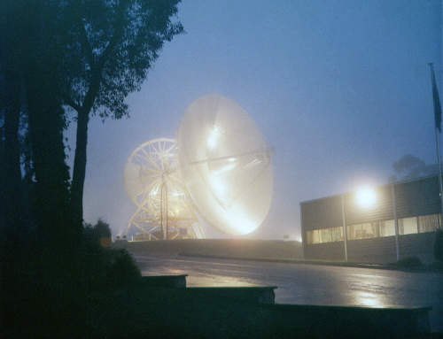
The Antenna in fog

The Honeysuckle Creek antenna in fog early one morning.

Larger photo – or here for one that’s been slightly straightened.

Photo: Hamish Lindsay.


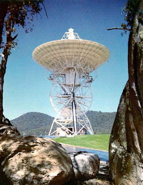
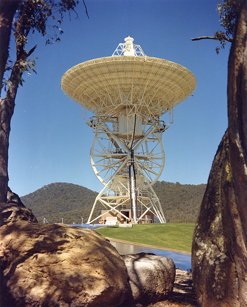
The 26 metre (85 foot) diameter steerable antenna was designed to be versatile – to be able to slew quickly enough to track spacecraft in Earth orbit (it could move at 3 degrees per second) and also be accurate enough to track spacecraft for hours at a time at lunar distances.

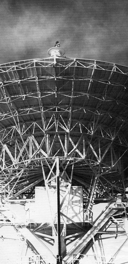
The Honeysuckle antenna was a cassegrain design – the incoming signal was focussed by the 26m primary parabolic reflector onto the secondary sub-reflector (at the top – supported by the quadrapod – the four-legged structure.) The signal then was reflected back down into the waveguide, through the hole in the centre of the dish, to the low noise amplifiers and then to the receivers.

The 20kW S-Band transmitter, coupled with the narrow beam width of the antenna, was ideal for communicating with spacecraft at lunar distances.

featured

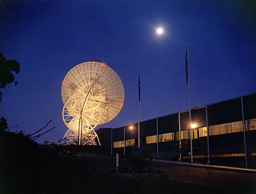
The Honeysuckle Creek antenna tracking the Apollo 15 CSM in its 68th revolution of the Moon on Wednesday 4th August 1971.

Photo: Hamish Lindsay.
Negative scan and image processing: Colin Mackellar.
(This image has been pushed to bring out details.)


The Honeysuckle antenna used an X-Y mount – two axes at right angles to each other.. This design meant that there were two ‘keyholes’ to the east and west where the antenna could not point.

In a 2003 e-mail, Hamish Lindsay wrote,

“The X-Y antenna at HSK was chosen because it could track a fast moving spacecraft directly overhead without interruption. The Az-El mount such as Parkes would have to spin madly around 180 degrees at zenith, so would lose the spacecraft. The deep space Hour Angle-Dec mount such as used at the Tidbinbilla 26 metre dish was designed for slow moving (siderial or star speed) targets, and only one axis was needed to drive the dish, but it could also happily track through zenith.”


HSK Antenna

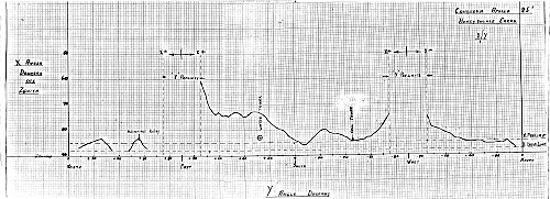
Horizon profile, West to East.
Drawn and scanned by Hamish Lindsay.

Larger. Largest.


HSK Antenna

Horizon profile.
Drawn and scanned by Hamish Lindsay.

Larger. Largest.


HSK Antenna

Horizon profile.
Drawn and scanned by Hamish Lindsay.

Larger. Largest.


HSK Antenna

Here’s Hamish standing on the apex of the antenna with his theodolite, surveying the Horizon profile. August 1971.

Photo preserved by Hamish Lindsay, scan by Colin Mackellar.


HSK Antenna

And here’s a scan of the 4x5 inch negative.

Photo by Hamish Lindsay, scan by Colin Mackellar.


HSK Antenna

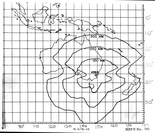
This December 1970 antenna profile, drawn by Hamish Lindsay, shows the coverage of the Honeysuckle antenna for a spacecraft at various heights in nautical miles. (1 nautical mile = 1.85 km).

The East-West keyhole – a mechanical pointing contraint caused by the design of the antenna mount – is easily seen.

Scan by Colin Mackellar.


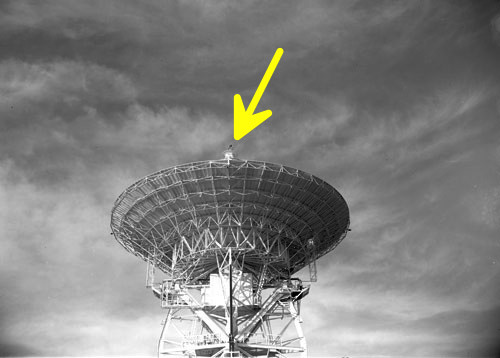
At the very top of the quadripod was the Acquisition Antenna used to help in acquiring low-earth orbit, fast moving spacecraft.


Featured

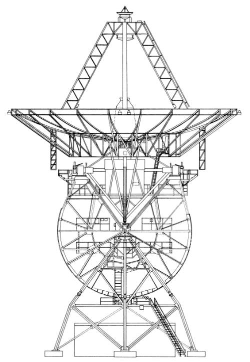
A schematic of the MSFN 26 meter Apollo antennas (installed at Honeysuckle Creek, Goldstone and Madrid).

Scanned and processed by Glen Nagle from a Collins Radio manual.


Featured

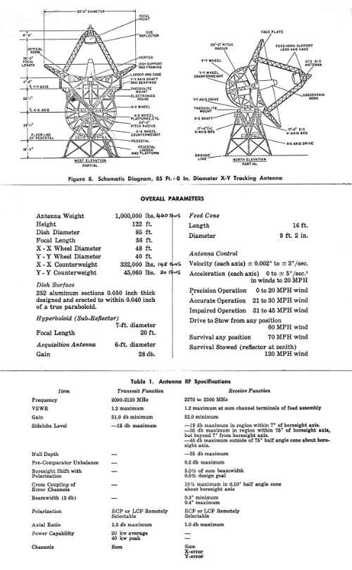
Mike Dinn preserved this photocopied information sheet, apparently assembled from a Collins Radio publication.
Scan: Colin Mackellar.


HSK antenna

The Honeysuckle antenna.

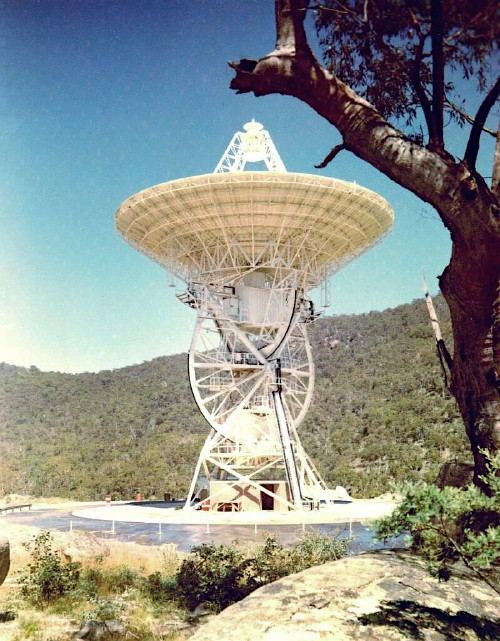
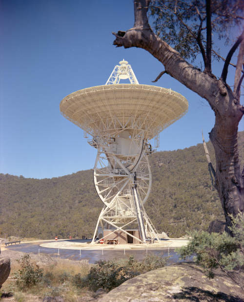
These three photos show the X-Y mount of the antenna.
The transmitter room is the square structure directly below the dish.

Photos by Hamish Lindsay, scan by John Saxon.
See updated scan below.


HSK early photo

The Honeysuckle antenna, 02 May 1968.

These two photos (particularly the lower one) show the X-Y mount of the antenna.
The transmitter room is the square structure directly below the dish.

Large, Larger (2.5MB).

Photo: Hamish Lindsay. Scan: Colin Mackellar from 8x10" print.


HSK antenna - X-Y mount

Photo: Hamish Lindsay.

See updated scan below.


HSK antenna - X-Y mount

The Honeysuckle antenna at stow, 14 February 1967.

Photo: Hamish Lindsay. A new scan from Hamish’s 4x5 inch negative by Colin Mackellar, August 2021.

(The date of photo corrected from a set of contact prints kept by Hamish.)


For Apollo, all television, tracking, remote commands and voice transmissions to and from the spacecraft were handled by a single radio carrier wave through a new ‘Unified S-Band System’.

Downlink data, monitoring several hundred measurements such as astronaut heart rate, cabin pressure and temperature was transmitted in real time.

From the tracking stations data and voice was set through NASCOM to the Goddard Space Flight Center in Maryland to be processed and passed on at 2400 bits per second to MCC computers at Houston.

Uplink data from Houston to the spacecraft, such as guidance commands were passed at 1200 bits per second via NASCOM and the command tracking stations...”


For more info on USB see The Unified S-Band Technical Conference proceedings.