
Goldstone Apollo Station, California
by Bill Wood
|
(Unless noted, all photos were
taken in May 1969, while tracking the Apollo 10 CSM in Lunar orbit.)
During all of the Apollo missions the Goldstone MSFN station
supported the flights using a two crew, 12 hour schedule. Because the Unified
S-band section operated both the Prime and Wing sites we had four crews. I had
one of the crews and had the title “USB Lead Engineer”.
When assigned to the Prime station the USB crew was composed of twelve
people:
four Receiver-Exciter,
one S-band Power Amplifier,
one Ranging/Timing,
one Antenna Position Programmer / Tracking Data Processor,
two Signal Data Demodulator System,
one Antenna Servo,
one Systems Monitor operator
and the USB Lead Engineer.
The SDDS people also operated the spacecraft Air to Ground console and remained at the Prime station.
When assigned to the Wing station the crew numbered ten with the same assignments minus the SDDS people.
The support crews were manpower intensive because of the need to manually operate many different pieces of equipment. The receiver-exciter alone had six racks of consoles to operate; two exciters and four receivers. The exciters were each handled by a single person while the receiver pairs were operated by one person each.
 |
|
Goldstone MSFN station, while tracking Apollo 10 CSM in lunar orbit, May 1969. Bill Wood is at left, standing. Photo: Bill Wood. |
Here are descriptions of what you see in the photo above from left to right:
 |
| USB System Monitor. Photo: Bill Wood. |
The first three racks are the USB System Monitor.
The operator on the stool takes care of three 8-channel strip chart recorders and a 100 event recorder.
These recorders sample many different equipment parameters that provide a graphical record of what happened in the different systems during a tracking period. The idea was to be able to review after the pass what happened and to explain and learn from problems encountered.
I personally used the strip chart recorders in real time
to alert the different equipment operators as to problems such as a receiver
locked to a side-band instead of the main carrier.
 |
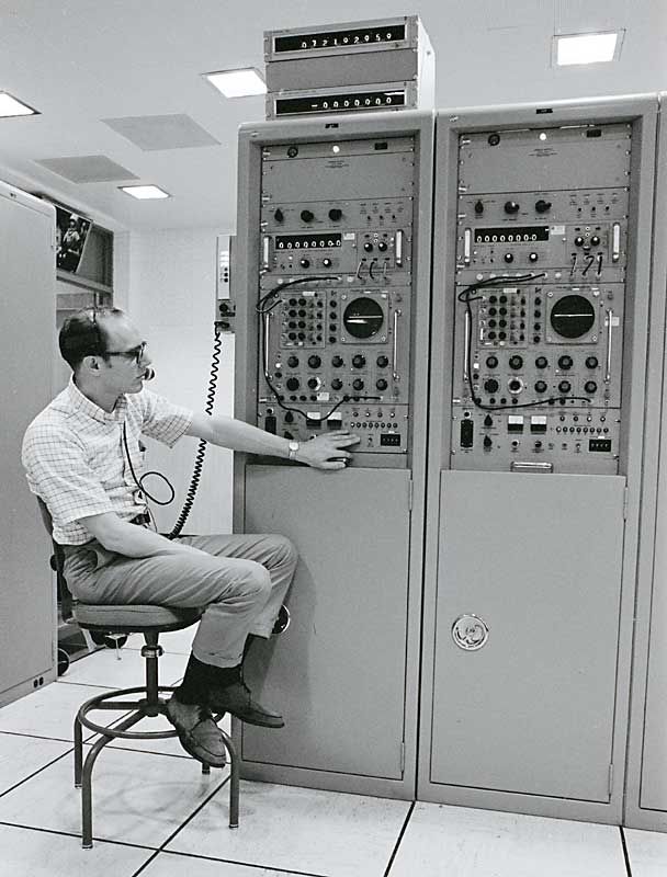
| 20 kW S-band power amplifier controls. Photo: Bill Wood. |
The next rack contained test equipment and other things that did not need operation
during spacecraft tracking. The fifth and sixth racks from the left contains
the 20 kW S-band power amplifier controls. It is operated by the person
with his face partially hidden.
Each 85-foot station had the capability to transmit
20 kW on both the CSM (2106 MHz) and the LM uplink (2102 MHz) frequencies if
necessary.
Then we come to the six receiver-exciter racks.
These are arranged in two groups of an exciter and two receivers.
On the left side is Exciter Nr 1 with Gary Malphrus operating it. This is normally the exciter assigned to uplink to either the CSM or the LM. Its associated receivers are the second and third rack from the left.
Tom Jonas, our R/E Engineer is operating both receiver 1 and 2.
To the right of these receivers is Exciter 2 which is being operated by Cheryl Place, one of the few female equipment operators we had. Exciter 2 is normally set up to take over from Exciter 1 in case of a failure. But it can also be used to track the second spacecraft in case there were a failure at the Wing site. (Part of the many redundant capabilities.)
Receivers 3 and 4 are being operated by one of our
equipment operators whose name I can not recall.
Speaking of equipment operators, Goldstone MSFN found it necessary to hire additional
people to fill out the operating crews. These people were hired locally in Barstow
and did not have the extensive GSFC training needed to maintain the various
systems. Cheryl and the other operator to her right were two of the roughly
eight R/E operators hired in this program. These people did an excellent job
and several went on to be full-fledged technicians in different parts of the
station.
 |
| Ranging. Photo: Bill Wood |
On the right side of the photo here
are the two Mark-1 ranging systems.
These amazing devices provided extremely accurate measurements of the range to the spacecraft and the rate of motion relative to the station. Houston was able to determine the absolute position of the spacecraft to within several meters when two 85-foot stations were tracking at the same time. This was made possible by the use of highly accurate time and frequency standards that used hydrogen masers developed by JPL for their deep space efforts.
 |
| Signal Data Demodulator System (SDDS). Photo: Bill Wood. |
This photo shows the five Signal Data Demodulator
System racks on the left.
Next is the racks containing the USB verification receivers and subcarrier demodulators. These sample the uplink and provide the data to the recorder section to be added to the data tapes. Next is a test equipment, switch matrix and Western Electric 112A Intercom panel.
The last tall rack on the right is the spacecraft air to ground console. Both the uplink and downlink voice signals are routed through the rack.
The short racks on the right are part of the Antenna Servo Console.
 |
| Servo controls. Photo: Bill Wood. |
The people in this photo from left to right are,
Tracy Nelson SDDS-A/G Tech, Tom Hardesty APP/TDP Engineer, Bob
Taylor Antenna Servo technician, and our Hydraulics technician, whose
name I can’t remember.
The servo racks are low and facing a large window (with the drapes pulled) that overlooks the 85-foot X-Y antenna when it is light enough to see it. This photo was taken on the evening shift after dark.
The antenna control console was unique in that the
control was what is known in the USA as a Duckpin ball. It is about 10 cm in
diameter is set into the console desk. Bob has his left hand on the ball. It
worked just like a computer track ball does today – only you were moving
about 250,000 kg about the sky!
The only time the operator moved the antenna with the ball was during acquisitions
and when setting up on the collimation tower. The small TV receiver in
the right hand rack was connected to a camera in the antenna that showed what
the antenna was pointed at. It had a 10 power catadioptic lens to see an optical
target on the collimation tower located about 3 km away on a hilltop. The rest
of the time it was positioned by the Antenna Position Programmer until
the receivers achieved lock. Then the antenna automatically followed the spacecraft
signal in the sky.
 |
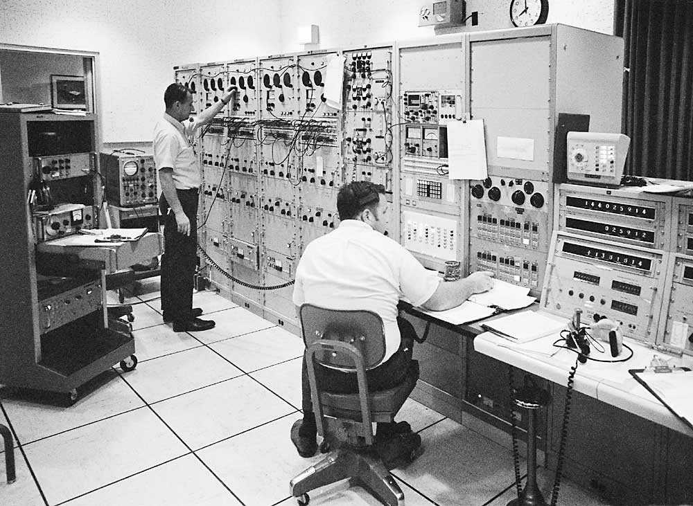
| USB section. Photo: Bill Wood. |
This shows the layout of the USB section looking west over the Antenna consoles.
On the extreme right side is the Hydrogen Maser frequency standard that made the pin-point positioning of the spacecraft on and around the Moon. It is next to the timing system, which I forgot to photograph at the time.
All these photographs were taken to give an 8 by
10" set to each member of the crew as a memento of their time at the
Goldstone Apollo station. Included in that set were color photographs of
the outside of the station such as the one below.
 |
| The Goldstone Apollo station. Photo: Bill Wood. |
This photo was taken in 1970. It shows the just
completed canteen building in the foreground. It must have been near a mission
because the Telco truck is parked by their microwave terminal.
Now is a good time to point out why the station was called the Apollo Station.
At Goldstone each station received the name of the first spacecraft it supported.
 |
| The Goldstone complex in 1996. Photo: Bill Wood. |
Unlike the Fresnedillas and Honeysuckle Creek 26-meter stations, the Goldstone Apollo station is still operating.
I took this photo in 1996 to show how it looks now.
My wide-angle lens was not wide enough to show yet another dish to the left of the frame here. It has three 34-meter diameter beam-waveguide dishes in addition to the modified 26-meter XY, a 9-meter XY antenna from Guaymas, Mexico, and a small 10-meter dish located closest to the camera. Tidbinbilla has similar 34-meter beam-waveguide dishes as well.
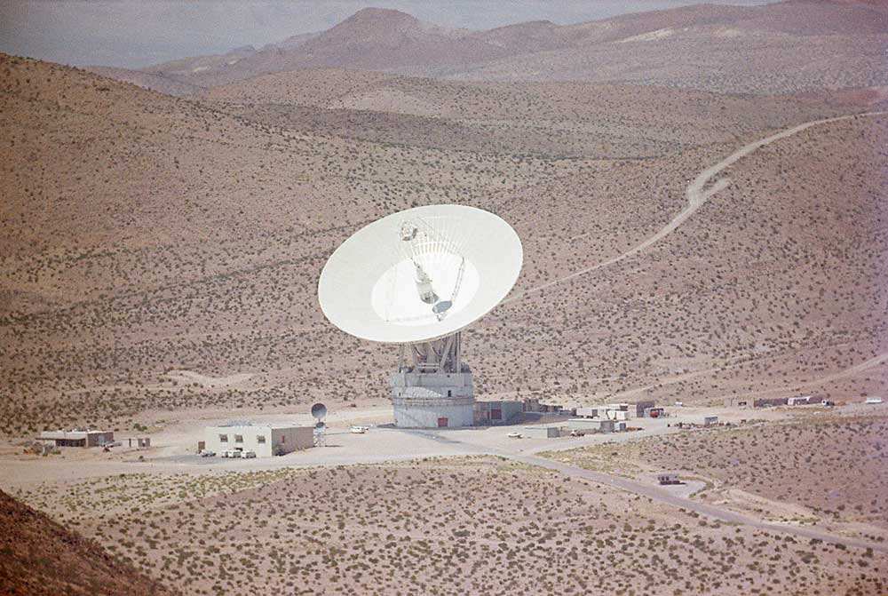 |
| The Mars antenna, June 1969. Photo: Bill Wood. |
Here is a photograph of the DSS-15 Mars 210-foot (64-meter) antenna taken
in June of 1969 in the exact configuration used for most of the Apollo missions.
It was taken with a 200 mm telephoto lens from at
the Apollo to Mars passive microwave repeater atop a peak between the two stations.
The top microwave dish next to the operations building is pointed directly at
us. The lower microwave dish was for communications between the Mars site and
the Echo site at Goldstone.