|
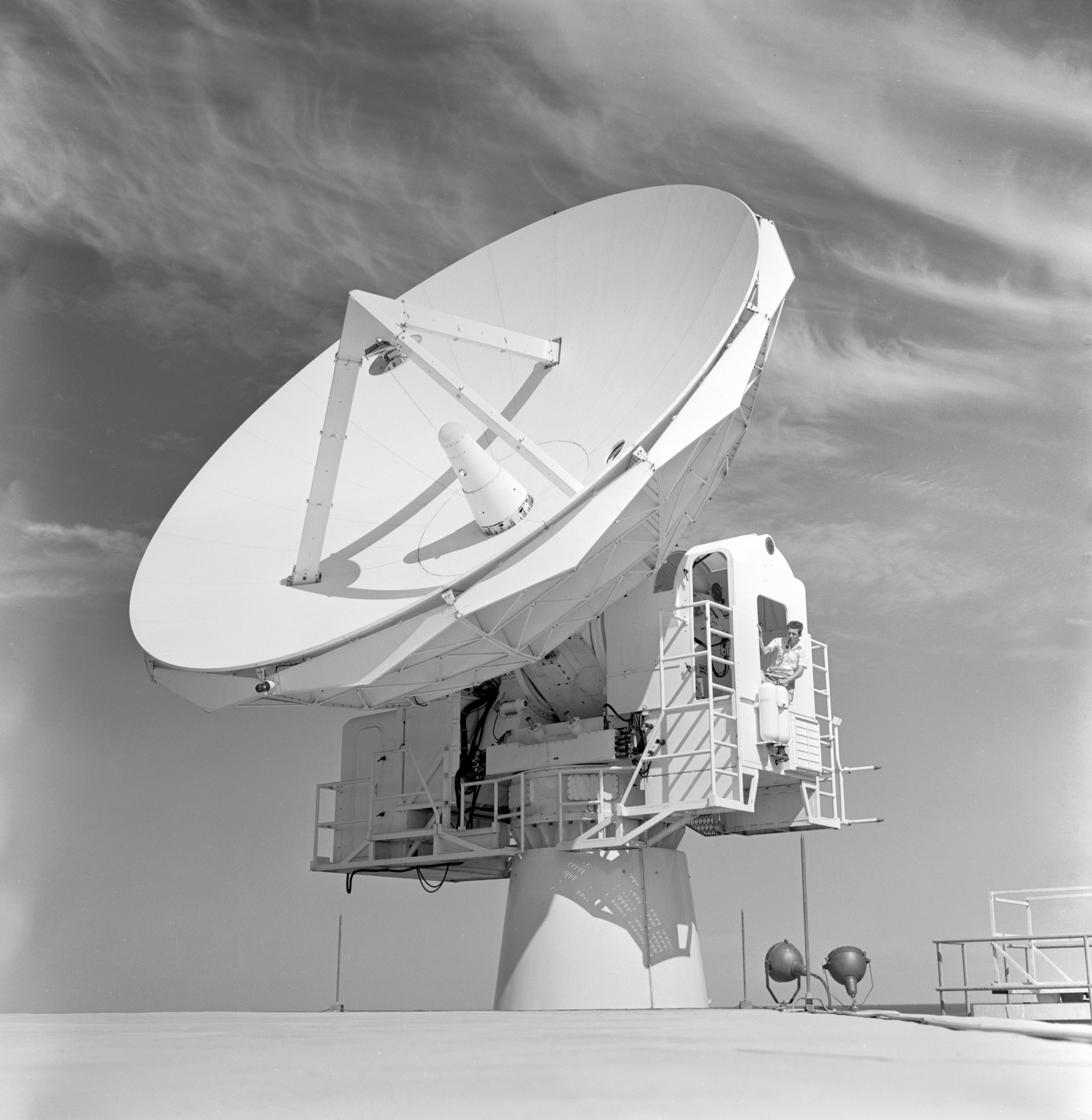
A close-up of the FPQ-6 dish with Don Blackman looking out of the antenna mount. Taken from the roof of the Q6 Operations building.
The data from the FPQ6 was the first time NASA had ground-based confirmation
that spacecraft, particularly the manned Gemini and Apollo spacecraft, launched from
Cape Canaveral had achieved the planned orbit.
Photo: Hamish Lindsay.
Updated negative scan: Colin Mackellar, 2026. |
Hamish Lindsay writes…
RCA’s Missile and Surface Radar Division developed
the FPQ6 skin tracking C-Band radar as a progression from their FPS-16 radar
already in use at Woomera.
It was capable of providing continuous spherical coordinate information at ranges
of 32,000 nautical miles (59,264 kilometres) with an accuracy of plus and minus
6 feet (1.8 metres). The FPS-16 only ranged out to 500 nautical miles (926 kilometres)
with an accuracy of 15 feet (4.57 metres), although it could be modified to
stretch out to 5,000 nautical miles (9260 kilometres).
The Q6 radar employed a 2.8 megawatt peak power (4.8 kilowatt
average), broad banded (5400 – 5900 MHz) transmitter with a frequency stability
of 1 x 10⁸.
The 8.8 metre dish antenna, using a cassegrain feed, had a 0.4°
beamwidth and a gain of 51 db. Its monopulse, 5 horn feed system permitted the
reference and error antenna patterns to have their gains independently established
as well as the slope of the error patterns optimised while supplying target
return signals to the receiving system with a minimum of insertion loss.
The three channel signal outputs of the antenna feed system
were supplied directly to the receiving system without undergoing any additional
loss-inducing signal manipulation with bandwidths optimised for the specified
pulse widths of 0.5, 0.75, 1.0 and 2.4 microseconds and the receiver noise figure
of 7.5 db was improved to 3.5 db through the addition of closed-cycle parametric
RF amplifiers. This system ensured a dynamic range in excess of 120 db.
The receiving system provided simultaneous presentation
of the skin and beacon returns to the console operator so that skin tracking
could be used if the beacon signal was lost.
The antenna pedestal was a high precision, two axis mount,
using a hydrostatic bearing in azimuth and phase roller bearings in elevation
to provide mobility and support to the counterbalanced, solid surface antenna.
The antenna was positioned through anti-backlash dual drive pedestal gearing
via a high torque-to-inertia electro-hydraulic valve motor system. A viscous
coupler located between the valve motor and pedestal drive gearing damped out
undesired mechanical resonances. The Q6 had a self contained digital computer,
an RCA FC-4101, whose primary purpose was to correct dynamic lag in the angular
output data.
The ground floor of the two storied building contained
the air-conditioning, transmitter heat exchanger controls, equipment load centre
data input junction box and ex-Mercury time standard
The first floor contained
the 8 banks of equipment racks, the console, and the 3 megawatt transmitter.
|
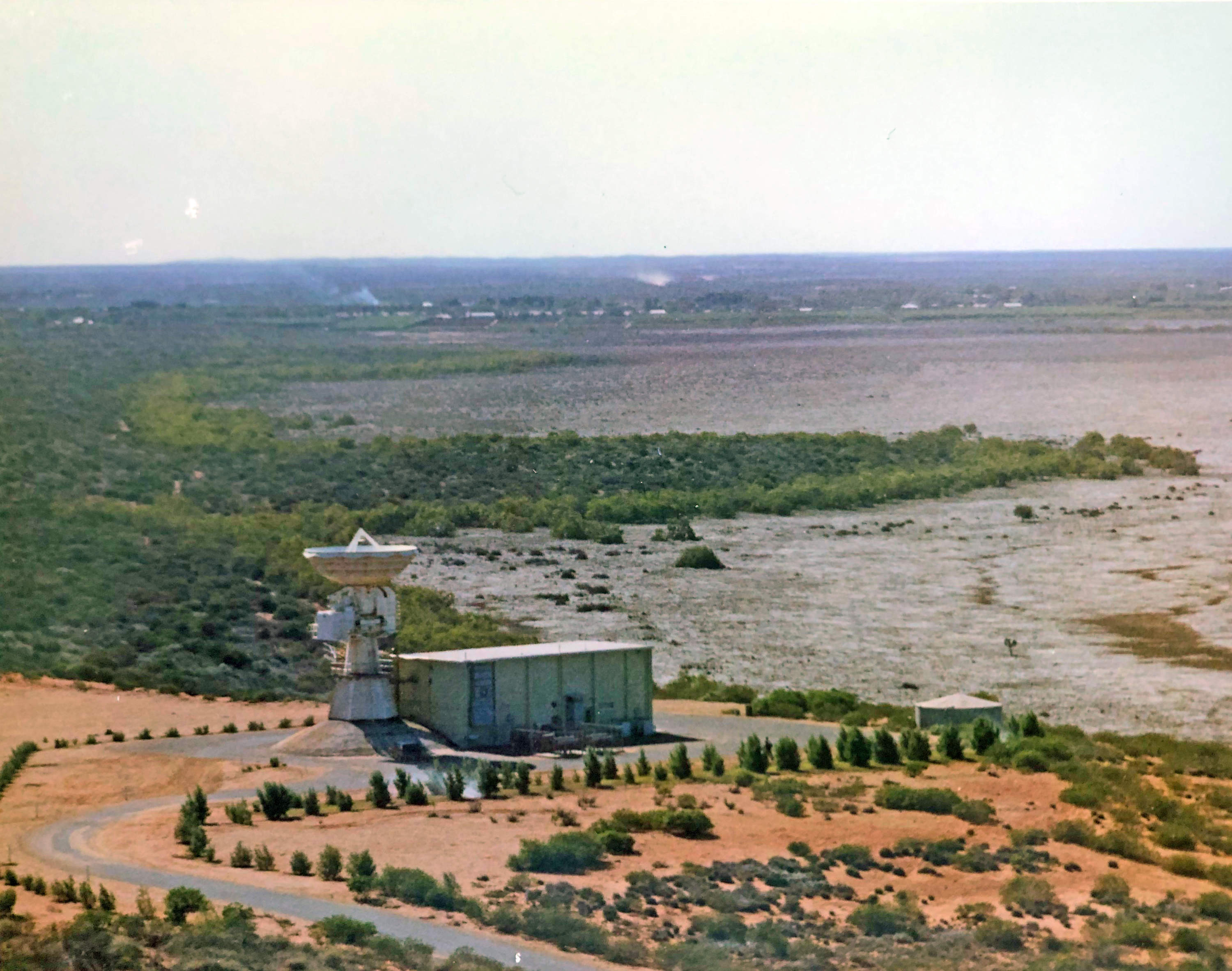
The FPQ6 with Tickle Belly Flats filled after recent rain – circa 1968.
This photo appears to have been taken from the top of the USB boresight tower, looking north.
Photo from the album presented to Station Director Lewis Wainwright at his farewell in 1968.
With thanks to Kevin Wainwright. Scan and enhancement by Colin Mackellar. |
Apart from looking after the time standard, one interesting
exercise I was involved in was tracking a balloon which was rocketed to the
upper atmosphere and threw out French chalk when it reached the specified height.
My job was to man a 20mm Oerlikon Mark 20 gunsight modified to connect to the
Q6 to slave it to follow the movements of the gun sight. I followed the rocket’s
French chalk it as it drifted with the upper atmosphere currents so the Q6 could
find and lock onto the signal to track the drift. I was very impressed when
I pushed my shoulders into the padded shoulder brackets and watched the dish
precisely follow my every movement. Gave me quite a feeling of power. I had
no trouble spotting the French chalk, but had to be quick setting the sights
on it as I could not see the rocket sending the balloon up until the chalk blossomed
out and dissipated fairly quickly, and then we had nothing to locate the balloon.
There were two firings, at dawn and dusk, with two teams to support them. Dusk firings were held on the 10th of May, 1965, and dawn firings on the 11th of May. The only systems called up were the Acquisition Aid, Verlort radar and FPQ6 radar plus the Control Room. Paul Linnane (Communications) and I (Timing) were also on duty and we operated the optical tracker.
It is interesting to quote from the operational instructions (4/65) issued by M&O Supervisor, Dick Simons, for this exercise.
“Stretchers will be available on the ground floor of the FPQ6 building for off-duty personnel. Staff are advised to bring the following items: Sleeping bags or blankets; towel; toilet gear; pillow case. Mattresses and pillows are provided.
Meal times will be from 30 minutes before, to 30 minutes after the change over period for the two teams.
Light refreshments (coffee, toast etc) will be available in the crew room at all times. Personnel may take advantage of this at any convenient time on request from the senior sub-system team member to the duty M&O.
The Control Room will be out of bounds to all staff during this operation.
The Visitor’s room will be out of bounds to all visitors during this operation.
The termination time should be shortly after the 11/1600 firing, but if it is not possible to launch all ten vehicles by this time, the firings will continue to a cut-off time of approximately 12/0400.”
|
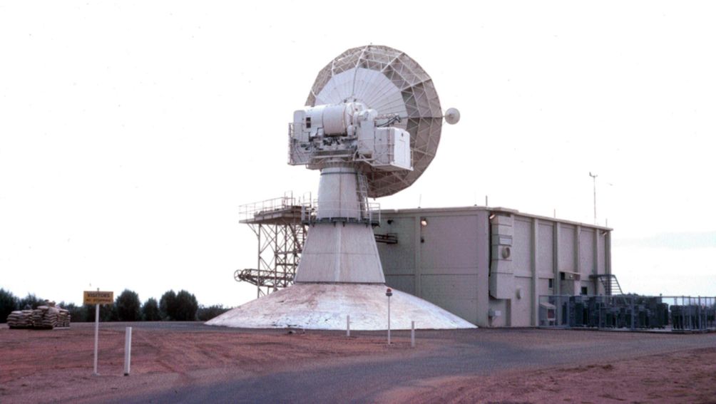
The FPQ6 antenna.
Photo: Tom Sheehan, 1971. |
|
|
The FPQ6 console in action.
From left: Ron Burgess,
diarist, George Allan and John Gerschwitz console operators,
and Len Algate, Engineer-in-charge on the right.
Photo: Hamish Lindsay. |
|
The first FPQ6 Supervising Engineer, Len Algate.
Trevor Housley, who succeeded Len at the Q6 recalls (January 2026):
“That is indeed a nice picture of Len. He was a real gentleman. He was the first Q6 Supervisor at CRO.
Peter Main, who was the original computer engineer at Q6, followed by his successor, Monte Sala, had moved up to the T&C building to work on the new UNIVAC 642B computers that were installed to support Apollo.
I was moved from DCS to Q6 as the computer/data engineer. Within a few weeks Len left to go to a new Tracking Station at Cooby Creek.
Site management then sent Lindsay Sage, who was the recently appointed Chief Engineer (I don’t know what his actual title was) to be an interim Q6 Supervising Engineer and, over the following couple of months, it must have become clear that I was able to handle the position. That made me, at 24, the youngest Supervising Engineer at CRO by at least 10 years.
The time I spent in that position, around 2.5 years or so, was the most interesting and satisfying period in my working life.”
Photo: Hamish Lindsay. 2026 negative scan by Colin Mackellar. |
|
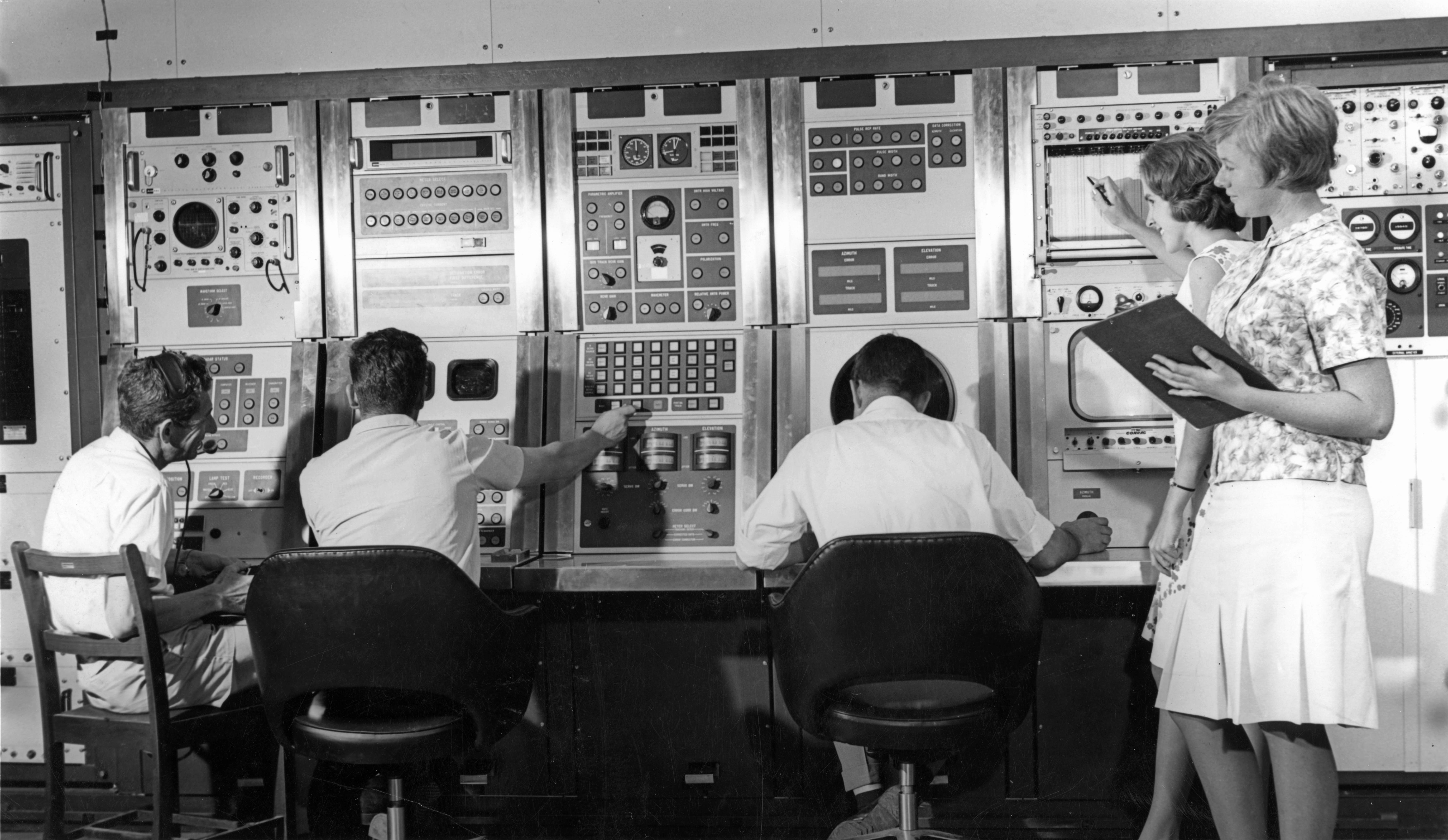
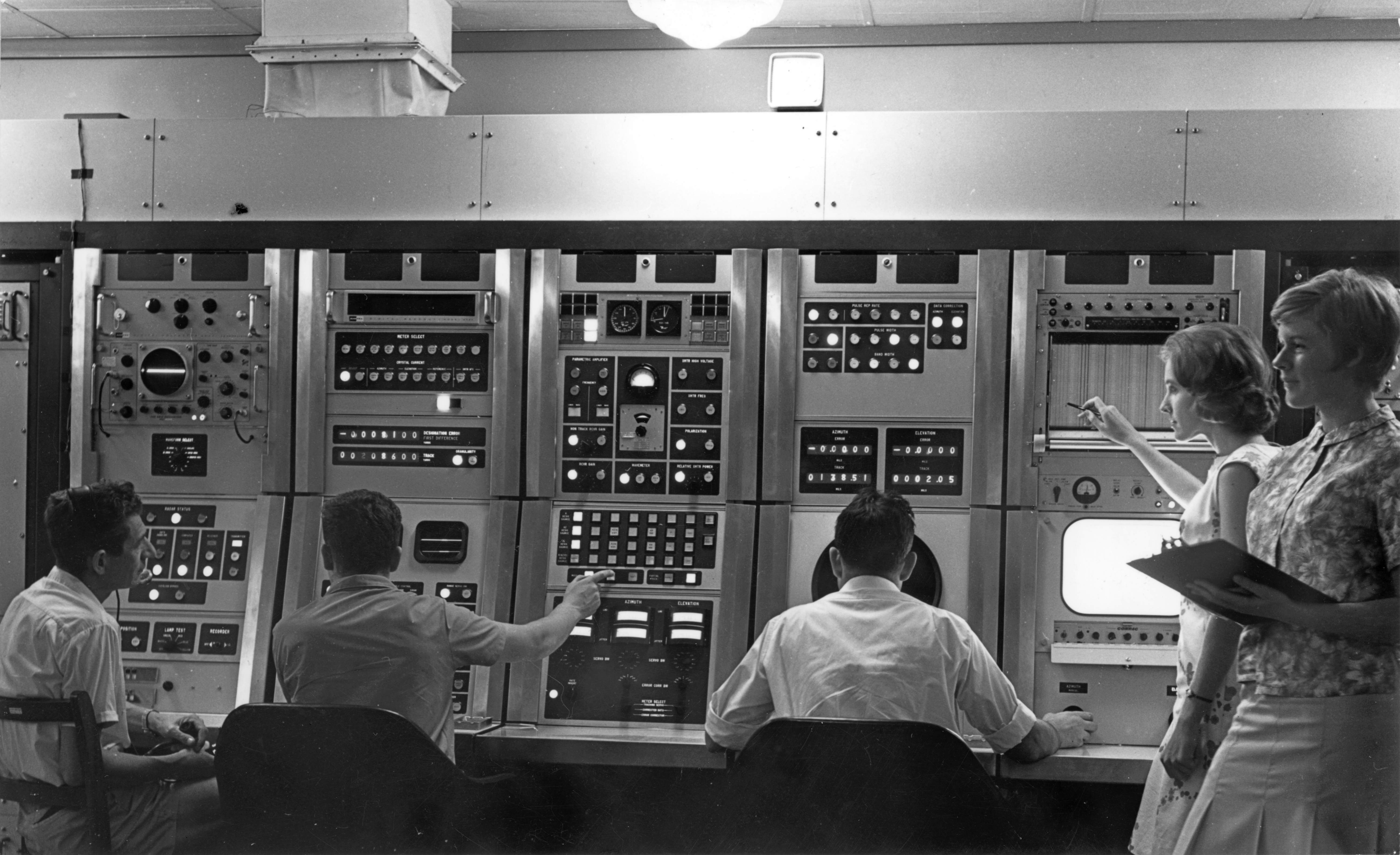
The FPQ6 console.
From left: Don Blackman, George Allan and (probably) Ron Burgess.
The two ladies are Diane Pitman with Nola Meikeljohn in the foreground. They were marking up the Sanborn Recorder to show events such as AOS and PCA (Point of Closest Approach).
Trevor Housley shares these memories (July 2024) –
“This photo was taken before my time at Q-6. Len Algate was the Supervising Engineer at the time and is to be seen in another photo of the Control Console.
Next to Don is George Allan - he was the Transmitter Technician and also the guy who had the gift to operate the A-scopes in order to pick the real signal out of the ground clutter as the spacecraft came over the horizon. George married a young lady named Rosie whose family owned one of the plantations on the Gascoyne River and George spent a lot, and I mean A LOT, of time trying to figure out how to automate the process of constructing the wooden boxes that were then used for transporting bananas.
The next chap, I’m going to guess based on the rolled up sleeves, is probably Ron Burgess. Ron was the Senior Technician and his specialty was the DIRAM – Digital Range Machine – and he is operating the ‘Angles’ i.e. the Azimuth and Elevation controls. Logically, one would think that the range machine tech would be the one to operate the A-scopes because the acquisition process was based on moving the range gate on the A-scope to the right spot to snap on to the incoming signal. However, George was young with quick reflexes and that was the skill that was needed.
In this photo, Ron is operating Az and El controls based on the ‘Look Angles’ that NASA had provided. Look angles were predictions of where the spacecraft was expected to be, in 20 second increments, during the pass. There were four parameters in the look angles i.e. Time, Range, Azimuth, Elevation.
The Q-6 beamwidth was 0.4 degrees so, for acquisition, we would point the antenna to the horizon where the spacecraft was expected to appear and we would typically scan the Azimuth plus and minus half a degree and George would look for the incoming signal as it advanced through the ground clutter and, when he was sure he had identified it, he would snap onto it.
He had to be careful because it was possible to acquire on a sidelobe rather than the main beam and that would lead to problems. We could not track on the first sidelobe because the Azimuth and Elevation error signals were reversed (in polarity) and would drive the antenna away from rather than towards the target. One could track on the second sidelobe but the antenna would wobble around a circular path around the target and the tracking data would have been useless.
When I joined Q-6 which would have been in 1965 some time, we closed the loop and gave the RCA 4101 computer the capability of directing the antenna to the required position at the right time. Originally based on the look angles and then based on ‘Orbital Elements’ or an ‘InterRange Vector’ which came from NORAD allowed us to calculate the exact position of the spacecraft at any instant and direct the antenna and the range gate accordingly. (The operators could override at any time.).
The 4101 would also calculate orbital elements from our own tracking data and we could forward those to Bermuda which was the only other Tracking Station with a Q-6 and we could also use our own elements to predict AOS on the next revolution.
The two ladies are Diane Pitman with Nola Meikeljohn in the foreground. They were marking up the Sanborn Recorder to show events such as AOS and PCA (Point of Closest Approach). The station managers had the idea that relatively untrained people could operate the equipment during tracking rather than utilising the more expensive technicians and engineers. This did work but, in those days, the equipment was not exactly of the ‘Set and Forget’ variety and the technical staff needed to be there at all times during operations to take care of the relatively frequent problems that could arise. Nola was one of the five daughters of Gordon and Myrtle Mieklejohn who ran the Carnarvon Hotel which could be found half way along the Fascine.”
Photo: Hamish Lindsay. 2025 scan by Colin Mackellar. |
|
The FPQ6 console.
In this photo, taken without flash lighting, backlit console displays are easily readable.
From left: Don Blackman, George Allan, (?) Ron Burgess, Diane Pitman and Nola Meikeljohn.
Thanks to Trevor Housley for the names.
Photo: Hamish Lindsay. 2025 scan by Colin Mackellar. |
Ken Anderson writes…
SOME NOTES ON THE AN-FPQ 6 RADAR
The AN-FPQ 6 radar was built by RCA and was, effectively, a development of the AN-FPS 16.
The Q6, as it was known by those who worked on it, was an amplitude comparison monopulse C-band radar, with a 2.8 MW peak klystron transmitter tunable from 5.4 to 5.8 GHZ, which had a 9 metre parabolic antenna, having 52 dB gain, a 0.6 degree beam width, utilising a Cassegrainian feed with a five horn monopulse comparator.
This radar had an unambiguous maximum range of 32,768 nautical miles, and employed uncooled parametric amplifiers with a system Noise Temperature of 440 K, [a Noise Figure of 4 dB]
A major features of the radar was its maximum unambiguous range of 32,768 nautical miles [58,512 kms] despite a Pulse Repetition Frequency [PRF] of some hundreds of pulses per second.
To combine these two features requires that the radar carry out Nth time around tracking, that is, it had to be able to track an echo resulting from a transmitted pulse other than that sent as the start of the same PRF period in which the echo was received.
In order to do so the range system employed a 2 second time base which allowed the system to determine the number of PRF periods elapsing before an echo, resulting from a particular Tx pulse was received. The range system carried out a find process, then a verify process before entering the auto-tracking mode.
[Note: All the following discussion uses ranges in yards – the radar was designed to work in those units and converting them to metric units would not add any clarity to this description.]
The FIND process is first carried out.
In this process two successive Tx trigger pulses are delayed by a time equivalent to an RF wave go and return distance of 16,000 yds. Then the range gate triggers are delayed by an equivalent time. The delayed Tx trigger pulses are counted in an auxiliary counter, the zone counter, until target video pulses are detected in the delayed range gates. At this point the zone counter contains the number of PRF periods corresponding to the Nth time around.
The VERIFY process is then entered. In this mode one Tx pulse is delayed for a 16,000 yd equivalent distance. The range gate in the zone determined in the FIND mode is also delayed to match the TX delay. This sequence is repeated until four video returns, from eight attempts, are received. When the four returns are detected automatic tracking is maintained.
The contents of the zone counter are added to the apparent range, that is the range reported in the current PRF period, to determine the actual range of the target.
If, during the Verify process four returns are not found after eight tries the Find process is re-initiated.
Take this example, in which a PRF of 640 PPS is assumed:
A target at a range of 4,883,072 yds is to be acquired.
At the radar console the operator initiates the FIND mode, and the system carries out that process by delaying triggers, counting zones etc., as described above, and finds that the zone counter has stored a count of nine. The VERIFY mode then takes place, resulting in confirmation of the zone count. The target will appear, on the radar display to be at a range of 273767 yds, that is the difference between, in this case, nine PRF period equivalents, plus the additional range. The range reported will be the actual target range of 4,883072 yds, the figure displayed on the range read-out.
As the radar was designed to track moving objects the need arose to handle targets which, in closing or opening range, during Nth time around tracking, came into coincidence with the next Tx pulse.
So, in the jargon, the radar had to be capable of tracking “through the Big Bang.” This arises from the fact that the antenna serves both the Tx and Rx. To allow this to happen a device called the Transmit-Receive Switch [T-R Switch] is used. The antenna is connected to the Rx until the Tx is pulsed. The T-R Switch detects the Tx pulse and transfers the antenna to the Tx for the duration of the pulse, say, 1 microsecond. [That period is that in which a radio wave would travel 164 yds. Remember we are talking here of radar ranges, the total go and return distance.]
At the instant the Rx is disconnected from the antenna the range system will lose track.
In order for an Nth time around tracking system to work there has to be some arrangement to cover the loss of Rx signal for the Tx pulse period.
In the radar under discussion this is achieved as follows.
|
The FPQ6 console in action – taken around 1969.
From left: Brian Davies, Geoff Linthorne, Mick Coffey.
Picture from Lloyd Bott’s collection via Ken Sheridan. Thanks to Tony Green and Trevor Housley for the IDs. |
When the target pulse reaches an apparent range of +/- 16,000 yds of the Tx pulse a number of Tx pulse, the number being the zone count, are delayed by a time equivalent to 32,000 yds. Take our example above.
When the range of the target reduces to 4625305 yds – that is 16000 yds greater than the 9 zones, the 32,000 yd delay is introduced into the Tx system. After 9 pulses the delay is transferred into the range gate generation system, and the target continues to be tracked. After the target has reached a range of 4593305 yds, 9 zones minus 16,000 yds, the delay is removed from the system. At that point the range is such that the zone counter will have been decremented by 1 and the apparent range will be 496145 yds, but with the target at a real range of 8 zones plus the apparent range.
Obviously, for an opening target the zone counter will be incremented and the apparent range will be slightly more than 16,000 yds.
|
Don Blackman (it looks like he’s holding his pipe) and the FPQ-6 skin tracking radar.
The 8.8 metre dish antenna had a beam width of 0.4° and a gain
of 51 db.
Photo: Hamish Lindsay. 2021 updated scan: Colin Mackellar. |
------